
What is OCRA MRI?
OCRA stands for Open-source Console for Real-time Acquisition. It’s a low-cost, open-source console (hardware controller) for MRI. Using the Red Pitaya board and some other hardware, we have created this console for under $500. On this site, you’ll find documentation on how to use it. We encourage you all to contribute to our github repository and make your own changes!
Goals of this project
In creating OCRA, our goals were to make an MRI console that is:
- Low-cost (<$500)
- Open source
- Capable of real-time control
By “real-time control”, we mean that it should be able to make changes in real time to the pulse sequence. In other words, we would like to be able to change the acquisition based on the data, or closed loop control. This is shown below: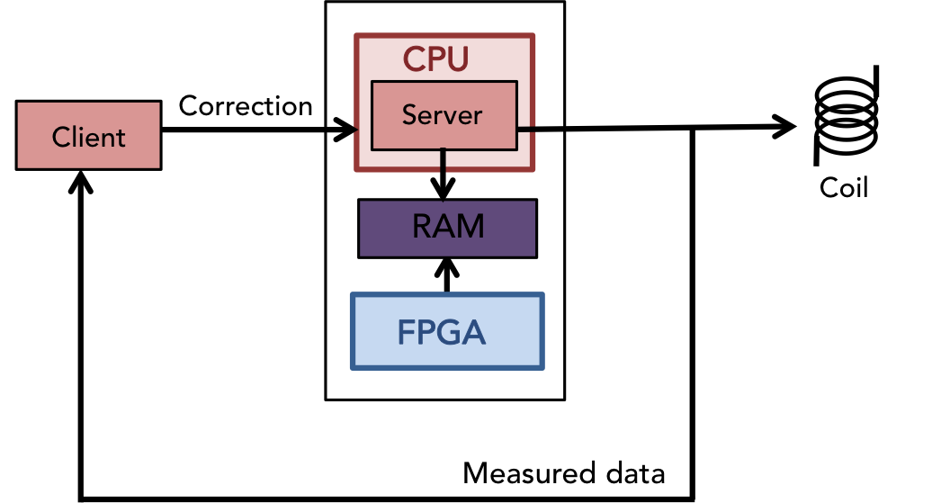
(We’ll explain each of the pieces in that diagram further).
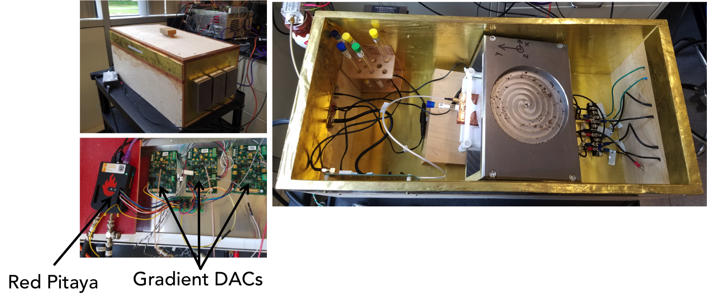
So far, we’ve used OCRA with the MGH/MIT Tabletop MRI scanners. These are educational scanners that are used in classes at MIT to teach students about MRI. There are currently 26 of them. The scanner that we used has a field strength of 0.4T, and an imaging Field-of-View (FOV) of 1cm. This is what our setup looks like:
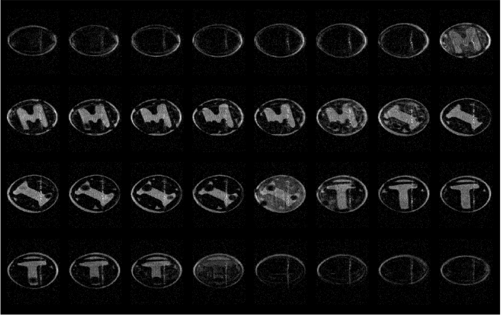
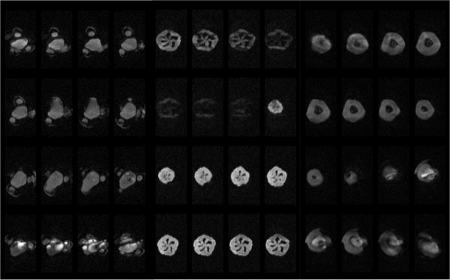
And here are some images that we’ve acquired with OCRA and the Tabletop:
Basic architecture
OCRA uses the STEMLab/Red Pitaya 125-14 board, commercially available for $329. The Red Pitaya uses a Xilinx 7010 Zynq SoC, which is a board that contains a Xilinx FPGA, dual-core ARM CPU, and shared RAM. It is pictured here:
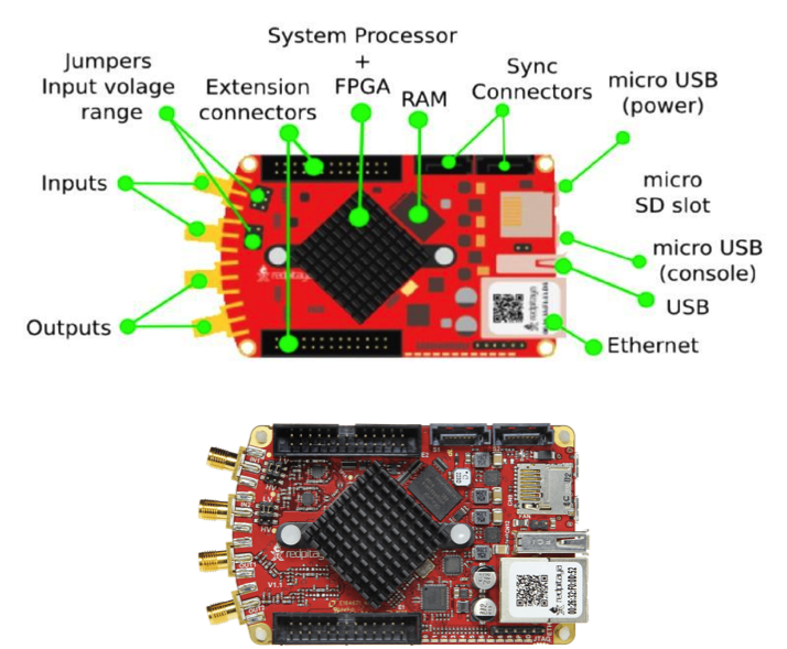
Additionally, the Red Pitaya has some RF hardware:
- 2 RF Tx outputs
- 2 RF Rx inputs
- 2 14-bit, 125 Msps ADCs
- 2 14-bit, 125 Msps DACs
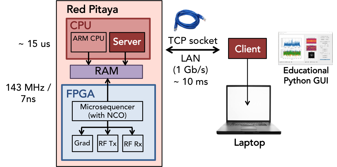
The FPGA executes the pulse sequence on the hardware, while the CPU receives updates from an external client. The FPGA and CPU can operate independently of one another. We call this an Asymmetric Multiprocessing System. This means that, while the FPGA plays out a waveform, the CPU can update it. This is how we get real-time control!
In our case, the client is a Python-based GUI. On the CPU, we have a server (written in C) that communicates with the client via an Ethernet connection. The Red Pitaya is connected to a LAN via the Ethernet connection, and it communicates wirelessly with other devices (e.g. a laptop) via the LAN.
Server-client model
The server is simply a C program that is run on the Red Pitaya. It has to be compiled with the ARM cross-compiler arm-linux-gnueabihf-gcc. We use the Vivado environment from Xilinx to compile the code. The server communicates with the client (the Python GUI) using TCP sockets. A diagram is shown below:
The Python GUI is intended as an educational tool for students to learn about MRI.
For more details on the hardware and software, check out the rest of the pages!