
Overview
The core of the OCRA project is the microsequencer, a softcore processor implemented in the FPGA to ensure real-time execution. This processor supports a very small instruction set that allows the convenient construction of real-time event tables and basic looping over the tables. An event-table describes the time at which an event is to happen inside the program. The most common such event is the production of a pulse waveform, such as a RF pulse or a gradient pulse, and the gating of the signal receiver. As result, the totality of these event tables is also called a pulse sequence, as it describes the precise timing and sequence of the pulses being played out by OCRA as part of a NMR/MRI experiment.
At the lowest level, the microsequencer can be programmed in a compact assembly-like language describing these tables. This language is designed to be machine generated, assuming there would always be either a UI-based or higher-level language generating the micro-sequencer instructions, but for very simple experiements, even basic imaging, these can be easily human written. The biggest down-side of human written microsequencer code is that the timing isn’t easily parameterizable, as the microsequencer has no math capabilities, and the python assembler as of now cannot evaluate literal math expressions (anyone interested in implementing that, please contact me).
The microsequencer reads its instructions from a memory block (more details in the PS interface description below), and its execution state can be controlled from the ARM over a set of control registeres described in the PS interface section below.
The events the sequencer controls are expressed by a 64-bit register, “pulse register”, where each bit is connected to a particular hardware event. A description of the available events for the OCRA can be found below. The pulse sequence is responsible for maintaining the state of that pulse register. The command PR copies the contents of a 64-bit register in the microsequencer to the pulse register, therefore updating the state of it immediately. This means, the pulse sequence code must maintain the state of all events at all times. Commands that allow updating individual bits by OR operation on the state, or XOR operation on state have not yet been implemented, but might make useful additions in the future.
Microsequencer Instructions
All instructions for the microsequencer are 64-bit wide, with a 6-bit opcode identifying the instruction in the most significant bit. The microsequencer features 16 general purpose 64-bit wide registers, denoted R0...R15 that can be
used as parameters to some of the instructions. When an instruction takes a register index as argument, its usually denoted as Rx in the manual.
Some instructions have a delay argument, which is a literal constant denoting the time to the next event in clock cycles. For OCRA, one clock cycle is exactly 8 nanoseconds (FPGA clock set to 125MHz). The delay argument is 40-bit wide. If longer delays are needed, the instruction can be repeated creating another delay.
When instructions have a addr argument, this refers to word address in the pulse sequence memory, and a microsequncer word is 64-bit wide. The microsequencer cannot address bytes, and it doesn’t need to.
There is several formats these instructions come in:
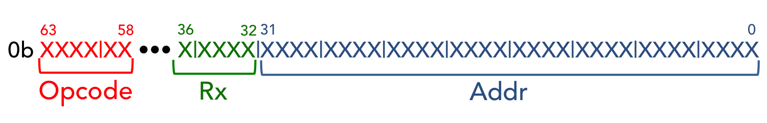
Format A:
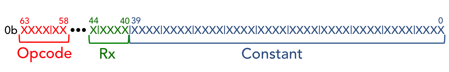
Format B:
Format C: Need a figure, but it is identical to format B, with no register argument
Table of all instructions:
| Instruction | Opcode | Format | Description |
|---|---|---|---|
NOP |
0b000000 | – | Do nothing |
HALT |
0b011001 | – | Halt the sequence |
DEC Rx |
0b000001 | A | Decrement register value of Rx by 1 |
INC Rx |
0b000010 | A | Increment register value of Rx by 1 |
LD64 Rx, addr |
0b000100 | A | Load 64-bit integer from address addr to Rx |
JNZ Rx, addr |
0b010000 | A | jump to addr if Rx != 0 |
J addr |
0b010111 | A | Unconditional jump to addr |
PR Rx, delay |
0b011101 | B | Pulse register Rx followed by a 40-bit delay in clock cycles |
TXOFFSET offset |
0b001000 | B | Set offset of Tx (RF) pulse to offset |
GRADOFFSET offset |
0b001001 | B | Set offset of gradient pulse to offset |
LITR delay |
0b000011 | B | Indicate end of TR, followed by 40-bit delay |
RASTCSYNC clkmask |
0b000101 | C | Reset raster clocks indicated in clkmask |
NOP
This instruction literally does nothing
HALT
This instruction ends the pulse sequence.
LD64
PR
J and JNZ
DEC and INC
RASTCSYNC
This instruction resets the raster clock of the clock indicated in the mask to start with the current clock cycle. All raster clocks in the OCRA are derived directly from the master clock of the FPGA by a divider, and are therefore ALWAYS synchronous. In order to start a raster clock cycle with a TR for example, the phase of the raster clock needs to reset with the beginning of the TR. This is accomplished by using this instruction at the beginning of the TR.
GRADOFFSET and TXOFFSET
LITR
Tutorial
Microsequencer PS interface
Old section, please ignore everything below
Sequence Programming
Pulse sequences are written in an Assembly-like language. Fundamentally, the language specifies events (e.g. turning on an amplifier gating signal) by writing to and reading from registers. At the lowest level, the FPGA determines the event type by an 8-bit number written to a register, where event is specified by one bit. The pulse bits are described in the table below:
| Bit | Description |
|---|---|
| 0 | Tx Pulse |
| 1 | Rx Pulse |
| 2 | Grad Pulse |
| 4 | Tx Gate |
| 5 | Rx Gate |
The unspecified bits are unused. These bit patterns can be grouped into four groups specific to execution:
- Wait
- Fire RF pulse
- Fire Gradient pulse
- Fire RF and gradient pulses
Each of these functions can be carried out with the receiver on and the receiver off, thus yielding 8 total possible groups. The bit RX_PULSE has inverted logic, so when it is on, the receiver is off. This is summarized in the table below. Here, OR refers to the bitwise OR operation.
| Command | Hex code | Description |
|---|---|---|
| RX_PULSE | 0x2 | All off/wait |
| 0x0 | 0x0 | Only receiver on |
TX_GATE OR TX_PULSE OR RX_PULSE |
0x13 | RF pulse |
TX_GATE OR TX_PULSE |
0x11 | RF pulse with receiver on |
GRAD_PULSE OR RX_PULSE |
0x6 | Gradient pulse |
| GRAD_PULSE | 0x4 | Gradient pulse with receiver on |
TX_GATE OR TX_PULSE OR GRAD_PULSE OR RX_PULSE |
0x17 | RF and gradient pulse |
TX_GATE OR TX_PULSE OR GRAD_PULSE |
0x15 | RF and gradient pulse with receiver on |
The assembly-like language specifies low-level operations on registers. The language is specified by 64-bit words. However, because the bus between the ARM CPU and RAM is 32 bits, these words must be specified in two 32-bit integers. The bit order is little-Endian, meaning that the first 32-bit integer is the operand, and the second 32-bit integer contains the opcode. Like Assembly, there are commands to JMP to an address in memory, LD64 a 64-bit integer into memory, and PR pulse a register for a certain amount of time. Each command is specified by a 6-bit opcode. The full list of commands is shown below.
| Instruction | Opcode | Format | Description |
|---|---|---|---|
| NOP | 0b000000 | – | Do nothing |
| HALT | 0b011001 | – | Halt the sequence |
| DEC Rx | 0b000001 | A | Decrement register value by 1 |
| INC Rx | 0b000010 | A | Increment register value by 1 |
| LD64 Rx, Addr | 0b000100 | A | Load 64-bit integer from address Addr to Rx |
| JNZ Rx, Addr | 0b010000 | A | Jump to Addr if Rx! = 0 |
| J Addr | 0b010111 | A | Jump to Addr |
| PR Rx, Delay | 0b011101 | B | Pulse register Rx after 40-bit Delay |
| TXOFFSET Offset | 0b001000 | B | Set offset of Tx (RF) pulse to Offset |
| GRADOFFSET Offset | 0b001001 | B | Set offset of gradient pulse to Offset |
There are two formats for instructions: Format A and Format B. In both formats, the highest 6 bits are used for the opcode. In Format A, bits 36:32 specify the register to operate on, while the lower 32 bits specify an address in memory. In Format B, bits 44:40 specify the register, and the lower 40 bits specify a constant. Formats A and B are illustrated below.
Format A:
Format B:
We provide a number of example sequences. In the basic folder, there is a sequence for spin echo (se_default.txt) and FID (fid_default.txt).
The spin echo sequence has a TE of 10ms.
In the img folder, there are a number of sequences for different image acquisitions. Use the txt file
that is not prepended with hex - for instance, in the 0 se folder, use se.txt, not se_hex.txt. The hex
txt file is an automatically generated file with the commands in hexadecimal, used for debugging. We provide the following sequences:
- Spin echo image (TE=10ms) -
0 se/se.txt - Gradient echo image (TE=1.7ms) -
1 gre/gre.txt - Slice-selective gradient echo image (TE=1.7ms) -
3 gre_slice/gre_slice.txt - Turbo spin echo (TE=10ms, ETL=2) -
4 tse/tse_etl2.txt - EPI (Gradient echo) -
5 epi/epi_gre_64.txt - EPI (Spin echo) -
5 epi/epi_se_64.txt - Spiral (Gradient echo) -
7 spiral/spiral_gre.txt - Spiral (Spin echo) -
7 spiral/spiral_se.txt
You can upload sequences to either the Signals GUI or the 2D Imaging GUI.